Infineon demonstrates functional SiC devices on 300-mm wafers
Infineon fabricated functional SiC power devices on 300-mm wafers in Villach and tested laser wafer separation in Dresden, but disclosed no yield data or volume-production date.
- By
- Grace Kim
- Filed
- Channel
- Chip Manufacturing
- Read
- 4 min read
By Grace Kim
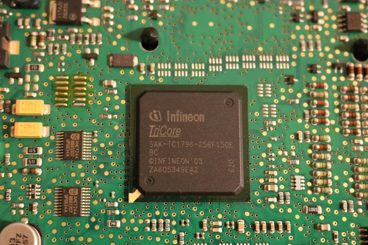
Infineon Technologies fabricated functional silicon-carbide (SiC) power devices on 300-mm wafers at its semiconductor plant in Villach, Austria. The substrate covers 70,686 mm², 2.25 times the 31,416 mm² area of a 200-mm wafer. That larger area could increase device output per processing cycle, although die size, edge exclusions, defect density and manufacturing yield determine the usable count.
Most commercial SiC power semiconductors historically have used 150-mm wafers. Manufacturers are now transitioning to 200-mm substrates. Infineon used existing silicon-processing equipment for the Villach run, demonstrating that an established semiconductor fabrication facility can process larger SiC substrates.
What has Infineon demonstrated?
Infineon fabricated the devices without disclosing device specifications, electrical test results, manufacturing yields, or any timetable for volume production. The company also tested a separate manufacturing idea at its Dresden, Germany, facility, where it assessed the 300-mm feasibility of its Cold Split wafer-separation process.
Siltectra developed Cold Split, and Infineon acquired Siltectra in 2018. One development concerns making devices on larger substrates. The other addresses crystal consumption during wafer separation.
Why does 300-mm processing raise tougher challenges?
SiC is substantially harder than silicon and has different mechanical and thermal properties, which complicate flatness, residual-stress control and material uniformity as the diameter expands. Manufacturers must also control defects that originate during crystal growth.
Threading dislocations, basal-plane dislocations and other crystallographic imperfections can reduce yield and influence device electrical characteristics and reliability. Larger substrates must remain mechanically stable through lithography, implantation, thermal processing and metallization. Process variations across the wafer can also change device characteristics.
Reusing silicon equipment could reduce capital needs for some fabrication operations. Silicon tools, however, cannot necessarily complete every SiC step without modification. Infineon did not identify the tools, changes or steps that required specialized SiC equipment.
Typical SiC processing combines ion implantation with high-temperature annealing to activate dopants. Activation temperatures commonly approach or exceed 1,600°C, far above those used in typical silicon CMOS processing.
Gate-oxide formation also needs careful control. Defects at the SiC/silicon-dioxide interface can trap charge, reduce channel mobility and affect threshold-voltage stability.
For SiC MOSFETs, relevant measurements include:
- Breakdown voltage
- Threshold voltage
- Drain-source on-resistance
- Gate leakage
- Off-state drain leakage
Infineon provided no wafer maps or statistical distributions for these parameters.
How does laser separation reduce SiC waste?
Conventional SiC wafer production uses diamond-wire saws to cut individual wafers from a cylindrical single-crystal boule. Material removed by the wire becomes kerf loss and cannot enter the resulting substrates.
The laser approach creates a controlled subsurface damage layer inside the crystal, after which a polymer layer and temperature-induced mechanical stress propagate a fracture along the modified plane. The separated wafer still requires surface finishing before device fabrication.
The method can reduce material consumed during separation. Grinding, polishing and process-related damage can still reduce usable-wafer yield. Infineon disclosed no measurements for material recovery, finished-wafer yield, surface roughness or process throughput.
How does Rayton's proton process differ?
California-based Rayton, founded in 2013, developed a different route to thin semiconductor substrates. Its particle accelerator implants protons at a controlled depth beneath a crystal's surface.
The implanted hydrogen ions create a buried damaged region that facilitates separation during later thermal processing. Rayton bonds the implanted surface to a carrier substrate before annealing, allowing a thin semiconductor layer to separate from the donor crystal while remaining attached to the carrier.
Rayton first developed the method for thin silicon photovoltaic wafers. The company later extended it to gallium arsenide, gallium nitride and SiC. It worked with Phoenix Nuclear Labs on proton-implantation equipment.
Both approaches seek to reduce consumption of expensive semiconductor crystal. Rayton targets thin transferred layers. Infineon's laser process can separate thicker, self-supporting wafers. Rayton's development has not established commercial-scale SiC substrate production. The companies have published no directly comparable manufacturing-cost or yield data.
The original author disclosed a small crowdfund investment in Rayton.
What could 300 mm change commercially?
SiC's wide bandgap and high critical electric field enable high-voltage devices with thinner, more heavily doped drift regions than comparable silicon devices. Those characteristics can reduce conduction resistance and support fast-switching power devices.
Target applications include:
- Electric-vehicle traction inverters
- Charging systems
- Industrial motor drives
- Renewable-energy converters
- High-power supplies
Increasing wafer diameter does not directly improve device electrical characteristics. Its potential advantage lies in manufacturing throughput and cost per acceptable device.
Infineon continues developing its 200-mm SiC manufacturing operations and has announced no date for 300-mm volume production. Commercial assessment requires electrical characterization across multiple wafers, yield data, reliability qualification and production-cost comparisons with established substrate sizes.
For now, the demonstration establishes neither production yields nor lower finished-device costs.
Where will Infineon show the wafer?
Infineon will display a processed wafer at electronica 2026, November 10–13, in Hall C3, Booth 502, at Messe München in Munich, Germany.
A 300-mm cost advantage will depend on repeatable yields, material recovery, surface quality and separation throughput, none of which Infineon has quantified. The company has set no date for 300-mm volume production.
Original: infineon.com
More from Grace Kim
Show full bio
Market editor covering people, launches and day-to-day practice in Semiconductors, chip manufacturing, hardware, AI compute at Chip Dispatch.
805 articles
Related articles
infineon-signs-200mm-sic-wafer-supply-deal-with-wolfspeed-7f8c8c3a
Infineon signs 200mm SiC wafer supply deal with Wolfspeed
infineon-completes-acquisition-of-c2i-semiconductors-ade108d2
Infineon Completes Acquisition of C2i Semiconductors
infineon-puts-1-1-billion-into-world-s-first-300mm-gan-fab
Infineon Puts €1.1 Billion Into World's First 300mm GaN Fab
infineon-closes-c2i-semiconductors-deal-to-bolster-ai-data-center-power-portfoli-24753901
Infineon Closes C2i Semiconductors Deal to Bolster AI Data Center Power Portfolio